MTP|MPO fiber cables are ideal for solving cable congestion problems in data centers or enterprises due to their flexibility, reliability, and scalability. However, network designers face another challenge: ensuring that array connections using multi-fiber MTP|MPO fiber cable always maintain the correct polarity. MPO|MTP fiber cables‘ polarity determines how the fibers are connected to ensure seamless signal transmission. The TIA 568 standard provides three methods for ensuring MTP®/MPO cabling systems operate with correct polarity, which will be described in this article.
What Is Polarity?
Polarity is a term used in the TIA-568 standard to explain how to ensure that each transmitter is correctly connected to the receiver at the other end of the multi-fiber fiber patch cord. Once the component is connected to the wrong polarity, the transfer process cannot continue.
Appropriate polarity ensures that the transmitted signal at one end of the channel matches the corresponding receiver at the other. We need to ensure that multiple optical fibers correspond correctly. All MTP|MPO connectors are equipped with a key and an indicator light (usually a white dot) to indicate the location of the first fiber. The direction of this key is critical to polarity. Three polarity methods are generally available in MPO|MTP cabling system: Polarity A, Polarity B, and Polarity C.
Once you select a way, you must stick with it throughout the channel. Let’s take a closer look.
Three Polarization Methods of MTP®|MPO Fiber Cable
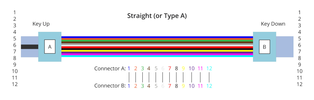
Type A (Straight-through): In this polarity, the fibers are straight-through, meaning that the transmit (Tx) fibers on one end are connected to the receive (Rx) fibers on the other end. For instance, if a fiber is located at position 1 (P1) of the connector on one side, it will correspondingly align with P1 at the opposite connector. The fiber sequence for a 12cores Type A MTP®|MTP fiber cable is depicted below:
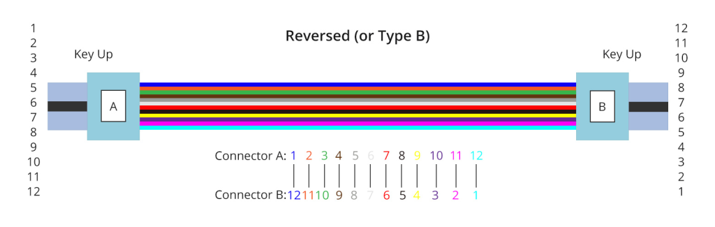
Type B (Reversed): Type B polarity reverses the positions of the Tx and Rx fibers at one end of the connection. The fiber corresponding to position 1 (P1) at one end is connected to the fiber at position 12 (P12) at the opposite end. The diagram below illustrates the fiber sequences of a 12cores Type B MTP|MPO fiber cable:
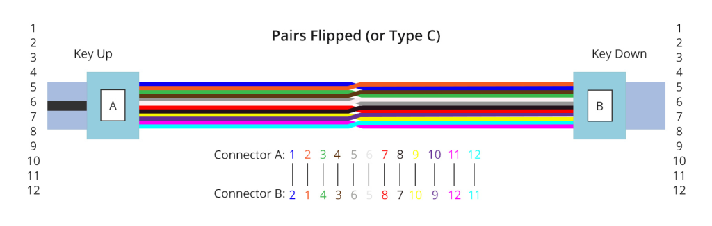
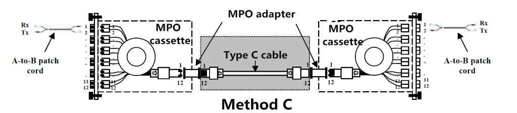
Type C (Pair-flipped): Type C polarity flips the positions of individual fiber pairs, rather than reversing the entire transmit and receive positions. This means that the fiber at position 1 at one end is shifted to position 2 at the opposite end, and the fiber at position 2 at one end is shifted to position 1 at the other end, and so on. The fiber sequence for an 12cores Type C MTP|MPO fiber cable is illustrated in the diagram below:
Polarity Connectivity Examples: Commonly Used 12-Fiber Applications
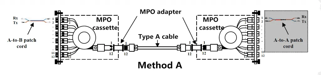
Polarity A MPO|MTP fiber cable is used for duplex applications, with standard A-B LC/SC fiber patchcord at one end and A-A LC/SC fiber patchcords at the other end to set the required correct Tx/Rx positions.
Polarity A MPO|MTP patch cord also used at one end of 40/100 Gig applications to connect the fiber optic patch panel ports to the corresponding transceiver ports. This setting requires the installation of a TypeB MPO patch cord at the other end of the channel.
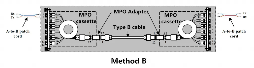
Polarity B MPO|MTP patch cords are used at both ends of a 40/100 Gig application to connect the fiber optic patch panel ports to the appropriate ports. This means that both duplex and parallel applications require the same type of patch cord, which is why polarity B is recommended chiefly.
Polarity C MPO|MTP cable is used when you need to disconnect the MTP|MPO cable to the duplex LC/SC connector, and you need to connect these connectors to Tx or Rx; use Polarity C. It would be best if you used pair inversion.
Another way to achieve this is to process the inversion on the MTP|MPO module at both ends. This method is preferred because you can convert the same cable to parallel optical fiber if necessary.
Conclusion
Network designers use MTP|MPO cable to meet the growing demand for higher transmission speeds. One of the biggest problems during this period, polarity can be solved by selecting the correct MTP|MPO cable, MTP|MPO connector, MTP|MPO distribution box, and fiber optic patch cable. Three different polarization methods can be applied to other situations to meet different application needs.
All kinds of duplex patch cables and MPO|MTP patch cables are available for AOFPLUS. For more information, you can contact us at sales@aofplus.com.