MTP®/MPO cabling system is the answer to solving cable congestion in data centers or enterprises, because it featured flexibility, reliability, and scalability. However, the network designers face another challenge: how to assure the proper MTP®/MPO polarity of these array connections using multi-fiber MTP®/MPO components from end to end. Maintaining the correct MTP®/MPO cable polarity across a fiber network ensures that a transmit signal from any type of active equipment will be directed to receive psa.ort of a second piece of active equipment and vice ver To ensure the MTP®/MPO systems work with correct polarity, the TIA 568 standard provided three methods, which will be introduced in this article.
MTP®/MPO Connector and MTP/MPO Polarity
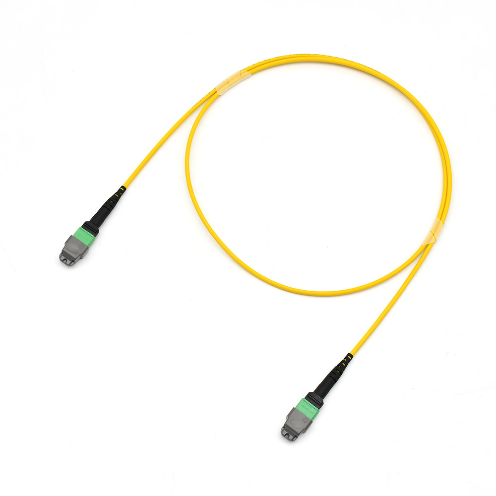
The MTP®/MPO Connector is a multifiber, high performance fiber optic connector that has enhanced optical and mechanical performance. The unique design (shown below) of the MTP®/MPO connector ensures the accuracy of the polarity in the MTP®/MPO network system.
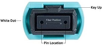
The Connector: An MPO/MTP connector has a key on the top or bottom of the connector body. There are two positions of the key, key up or key down. Key up position means that the key sits on top. When the key sits on the bottom, it is the key down position. Moreover, the fiber holes in the connector are numbered in sequence from left to right named as P1 (position 1), P2, etc. Each connector is additionally marked with a white dot on the connector body to designate the P1 side of the connector when it is plugged in. The MPO/MTP connector can be further divided into female connector and male connector. The former has no pins while the latter has two pins on the connector. The following picture shows the basic structure of MPO/MTP connector.
Three Cables for Three Polarization Methods
The three methods for proper polarity defined by TIA 568 standard are called Method A, Method B, and Method C. To match these standards, three types of MTP®|MPO fibers with different structures named Type A, Type B, and Type C are being used for the three different connectivity methods. First, we will discuss the three cable types, and then the three connectivity methods.
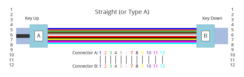
Type A MPO|MTP Cables, also known as straight cables, are straight-through cables with a key-up MTP® connector on one end and a key down MTP®|MPO connector on the opposite end. This makes the fibers at each end of the cable have the same fiber position. For example, the fiber located at position 1 (P1) of the connector on one side will arrive at P1 at the other connector. The fiber sequence of a 12 fiber MTP® Type A cable is shown below:
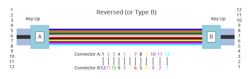
Type B MPO|MTP Cables: Type B cables (reversed cables) uses key up connectors on both ends of the cable. In this Method the fiber positions are reversed at each end. The fiber at P1 at one end is mated with fiber P12 at the opposing end. The following picture shows the fiber sequences of a 12 fiber Type B cable.
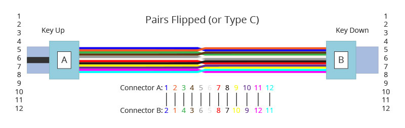
Type C MTP|MPO Cables: Type C cables (pairs flipped cables) looks like Type A cable with one key up connector and one key down connector on each side. However, in Type C each adjacent pair of fibers at one end are flipped at the other end. For example, the fiber at position 1 on one end is shifted to position 2 at the other end of the cable. The fiber at position 2 at one end is shifted to position 1 at the opposite end, and so forth. The fiber sequence of Type C cables is shown in the following image.
Three Connectivity Methods
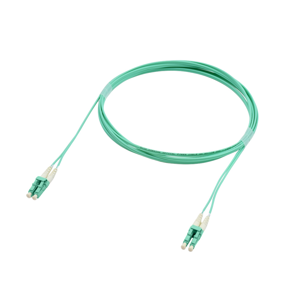
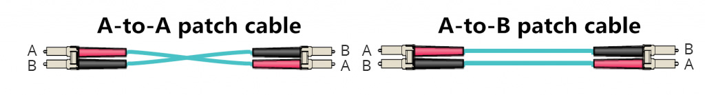
Different polarity methods use different types of MPO|MTP® trunk cables. However, all the methods should use duplex patch cables to achieve the fiber circuit. The TIA standard also defines two types of duplex fiber patch cables terminated with LC or SC connectors to complete an end-to-end fiber duplex connection: A-to-A type patch cable—a cross version and A-to-B type patch cable—a straight-through version.
The following part illustrates how the components in the MTP® system are used together to maintain the proper polarization connectivity, which is defined by TIA standards.
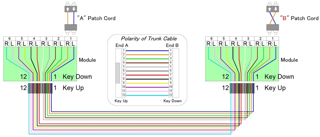
Method A: In Method A, type-A MPO/MTP® cable connects an MPO/MTP® module on each side of the link. In Method A, two types of patch cords are used to correct the polarity. The patch cable on the left is standard duplex A-to-B type, while on the right a duplex A-to-A type patch cable is used.
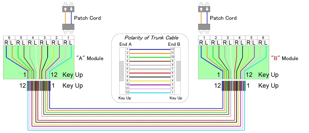
Method B: In method B, Type B MTP® cable is used to connect the two modules on each side of the link. The fiber positions of Type B cable are reversed at each end. Therefore, standard A-to-B type duplex patch cables are used on both sides.
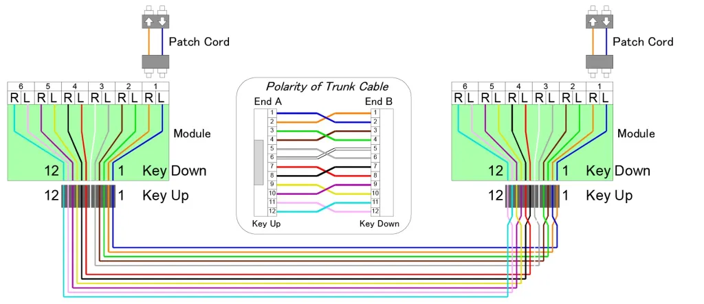
Method C: A pair-reversed method C cable is used in Method C connectivity to connect the MTP® modules on each side of the link. Patch cords at both ends are the standard duplex A-to-B type.
Keep MTP®/MPO Polarity Rules When Building Connection
It is very important that careful consideration be taken when adding MTP®/MPO cables to existing cabling in the network data center or enterprise application. Why? When fiber patch cords have different polarity and gender, it can be very easy to impact your cabling system transmission signal, rendering your entire cable link inoperable. That is why it is so important that IT staff and cabling technicians are very careful when replacing any patch cords in the field in an MTP®/MPO cabling system. Those who don’t understand polarity or are in a rush to get equipment up and running can potentially use the wrong patch cord and greatly impact the cable network.
Conclusion
More and more network designers are using MTP®/MPO assemblies to meet the growing demand for higher transmission speeds. When it comes to designing for MTP®/MPO applications, one big issue – polarity – can be solved by choosing the right type of MTP® cables, MTP® connectors, MTP® cassettes, and fiber optic cables. Regardless of which cabling solution you choose, there are three different polarity methods that can be applied based on system requirements in different cabling applications.