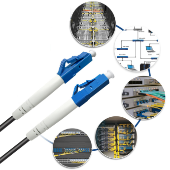
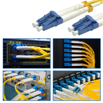
The connection methods for LC single-mode fiber optic patch cords are mainly divided into two categories: direct connection between devices and connection through fiber optic distribution equipment. The appropriate method can be selected based on the application scenario, equipment type, and wiring requirements. The following is a detailed explanation:

Direct Connection Between Devices
Suitable for short-distance, point-to-point transmission scenarios, such as direct connections between devices like servers and switches, or switches and routers.
Direct connection to device port
Operating Steps:
Confirm that the device port type is LC interface (e.g., optical module, switch port).
Insert one end of the LC patch cord into the TX (transmit) port of device A, and the other end into the RX (receive) port of device B (if the device is labeled TX/RX).
If the device port has no direction labeling (e.g., bidirectional port), you can connect them arbitrarily, but ensure that the protocols of both devices match (e.g., speed, wavelength).
Applicable Scenarios:
Short-distance transmission (e.g., interconnection of devices within a rack).
The device port directly supports the LC interface, requiring no intermediate conversion.
Precautions:
If the device port is labeled TX/RX, the direction must be strictly matched; otherwise, signal transmission may fail.
Avoid excessive bending of the fiber optical patch cord during direct connection to prevent signal loss.
Through the Optical Fiber Adapter (Flange) Connection
Operating Steps:
Prepare an LC-LC fiber optic adapter (square coupler).
Insert the two LC patch cords into both ends of the adapter to form a temporary or permanent connection.
Applicable Scenarios:
Scenarios requiring flexible adjustment of connection relationships (such as testing or temporary expansion).
When the distance between equipment ports is relatively far, requiring short patch cords to extend the connection.
Advantages:
No need to repeatedly plug and unplug equipment ports, reducing the risk of interface wear.
Facilitates quick replacement or adjustment of the link.
Connected by Fiber Optic Cabling Equipment
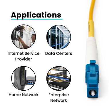
Suitable for medium-to-long distance transmission or centralized management scenarios, such as data centers and enterprise server rooms.
Connecting to Fiber Optic Distribution Frame (ODF)
Operating steps:
Insert one end of the LC fiber patch cord into the device port (e.g., switch), and the other end into the LC adapter of the ODF.
Connect the patch cord to the main fiber optic cable (e.g., incoming fiber optic cable) through the fusion splice tray or pre-connected module inside the ODF.
Applicable scenarios:
Medium-to-long distance transmission (e.g., cross-server room, cross-floor cabling).
Scenarios requiring centralized management of fiber optic links.
Advantages:
Easy to maintain and expand, allowing for quick replacement or testing of links.
Reduces signal loss through fusion splicing or pre-connection technology of the ODF.
Connecting to Fiber Optic Terminal Box (FTB)
Operating steps:
Insert one end of the LC fiber patch cable into the device port, and the other end into the LC adapter of the FTB.
Connect the pigtail inside the FTB to the incoming fiber optic cable through fusion splicing or cold splicing.
Applicable scenarios:
Home or small office network deployment (e.g., Fiber to the Home FTTH).
Scenarios requiring protection of fiber optic ports (e.g., to avoid dust and moisture).
Advantages:
Compact structure, suitable for space-constrained scenarios.
Provides physical protection for fiber optic ports, extending their lifespan.
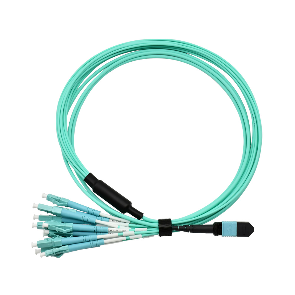
Connecting to Fiber Optic Splitter
Operating steps:
Insert one end of the LC patch cord into the device port (e.g., OLT optical line terminal), and the other end into the input port of the splitter.
Connect multiple LC fiber optic patch cords through the output ports of the splitter to achieve signal splitting (e.g., 1-to-8, 1-to-16).
Applicable scenarios:
Passive Optical Network (PON) deployment (e.g., GPON, EPON).
Scenarios requiring splitting a single optical signal to multiple users.
Precautions:
Splitters introduce signal attenuation (e.g., a 1-to-8 splitter attenuates by approximately 10.5dB), so ensure sufficient optical power from the device.
Select the appropriate splitter type based on the splitting ratio (e.g., equal splitting, unequal splitting).
Connection Methods for Special Scenarios
Circulator Connection
Operating Steps:
Insert an LC patch cord into port 1 (input) of the circulator, and another patch cord into port 2 (output), forming a unidirectional transmission link.
For bidirectional transmission, connect a reverse link through port 3 of the circulator.
Applicable Scenarios:
Scenarios requiring unidirectional isolation or bidirectional multiplexing (e.g., optical sensing, fiber optic testing).
Advantages:
Achieves unidirectional transmission of optical signals, avoiding reflection interference.
Saves fiber optic resources (e.g., single-fiber bidirectional transmission).
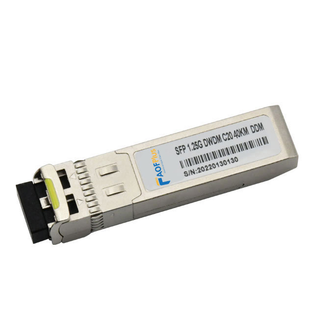
Wavelength Division Multiplexer (WDM) Connection
Operating Steps:
Insert LC fiber patch cables of different wavelengths into the input ports of the WDM (e.g., 1310nm, 1550nm).
Connect an LC patch cord through the common port of the WDM to achieve multiplexed transmission of multiple wavelength signals.
Applicable Scenarios:
Scenarios requiring expansion of fiber optic transmission capacity (e.g., CWDM, DWDM systems).
Advantages:
Transmits multiple signals on a single fiber, improving bandwidth utilization.
Supports long-distance transmission (e.g., DWDM systems can transmit hundreds of kilometers).
Connection Precautions
Cleaning the Interface:
Before each insertion and removal, clean the LC connector using a dedicated cleaning tool (such as a lint-free cotton swab and alcohol wipe) to prevent dust or dirt from causing signal loss.
Avoid Excessive Bending:
The minimum bending radius for LC patch cords is recommended to be ≥30mm. Excessive bending may lead to fiber breakage or increased signal attenuation.
Confirm Polarity:
In dual-fiber bidirectional transmission scenarios, distinguish between transmitting and receiving patch cords using color or labels to ensure correct link polarity.
Test Link Performance:
After connection, use an OTDR (Optical Time Domain Reflectometer) or optical power meter to test link loss and ensure performance meets specifications (e.g., insertion loss ≤0.5dB).